Tilting & De-centering Components
Complex ray tracing through misaligned or deliberately folded optics.
Introduction
This tutorial shows how to tilt and de-center surfaces in a lens. We will use a spot diagram to show how ray intersection on the image plane are impacted by tilt/decentering.
Core concepts used
Step-by-step build
Set up and examine the baseline aligned lens
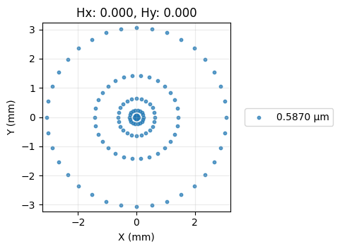
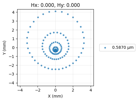
Import the required libraries, build a simple singlet with all surfaces perfectly aligned, draw the layout, and view the baseline spot diagram.
import numpy as np

from optiland import analysis, optic

lens = optic.Optic()

# add surfaces
lens.add_surface(index=0, radius=np.inf, thickness=np.inf)
lens.add_surface(index=1, thickness=7, radius=19.93, is_stop=True, material="N-SF11")
lens.add_surface(index=2, thickness=21.48)
lens.add_surface(index=3)

# add aperture
lens.set_aperture(aperture_type="EPD", value=25.4)

# add field
lens.set_field_type(field_type="angle")
lens.add_field(y=0)

# add wavelength
lens.add_wavelength(value=0.587, is_primary=True)

lens.draw(num_rays=10)

spot = analysis.SpotDiagram(lens)
spot.view()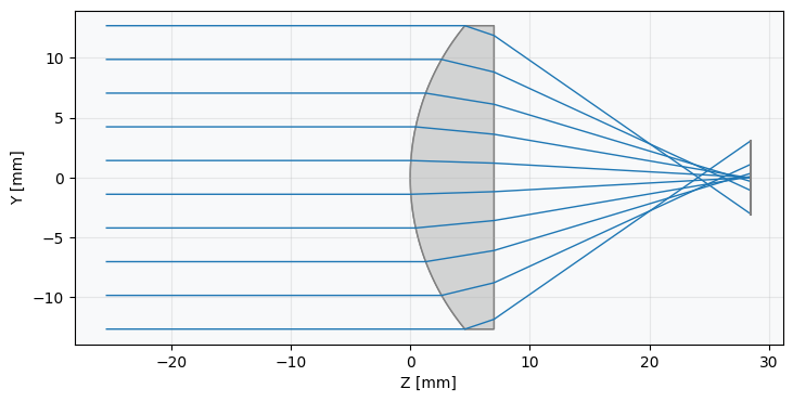
Tilt the first surface by 5° and observe spot degradation
Now, let's tilt the first surface by 5 degrees and redraw the lens.
lens = optic.Optic()
# add surfaces
lens.add_surface(index=0, radius=np.inf, thickness=np.inf)
# == WE ADD THE TILT TO THIS SURFACE ===============
lens.add_surface(
index=1,
thickness=7,
radius=19.93,
is_stop=True,
material="N-SF11",
rx=np.radians(5.0),
)
# ==================================================
lens.add_surface(index=2, thickness=21.48)
lens.add_surface(index=3)
# add aperture
lens.set_aperture(aperture_type="EPD", value=25.4)
# add field
lens.set_field_type(field_type="angle")
lens.add_field(y=0)
# add wavelength
lens.add_wavelength(value=0.587, is_primary=True)
lens.draw(num_rays=10)
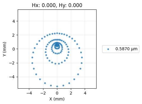
spot = analysis.SpotDiagram(lens)
spot.view()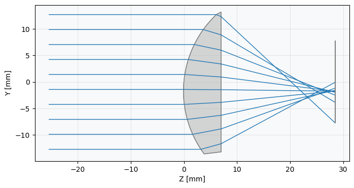
Decenter the first surface by 1 mm and compare
Let's decenter the first surface of the lens.
lens = optic.Optic()

# add surfaces
lens.add_surface(index=0, radius=np.inf, thickness=np.inf)

# == WE DECENTER THIS SURFACE =====================
lens.add_surface(
 index=1,
 thickness=7,
 radius=19.93,
 is_stop=True,
 material="N-SF11",
 dy=1.0,  # 1 mm decenter
)
# ==================================================

lens.add_surface(index=2, thickness=21.48)

lens.add_surface(index=3)

# add aperture
lens.set_aperture(aperture_type="EPD", value=25.4)

# add field
lens.set_field_type(field_type="angle")
lens.add_field(y=0)

# add wavelength
lens.add_wavelength(value=0.587, is_primary=True)

lens.draw(num_rays=10)

spot = analysis.SpotDiagram(lens)
spot.view()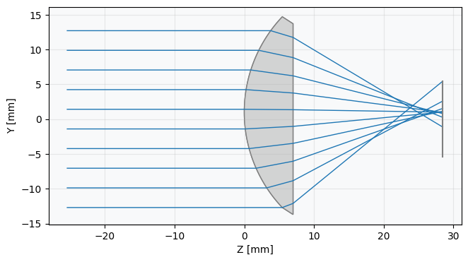
Show full code listing
import numpy as np

from optiland import analysis, optic

lens = optic.Optic()

# add surfaces
lens.add_surface(index=0, radius=np.inf, thickness=np.inf)
lens.add_surface(index=1, thickness=7, radius=19.93, is_stop=True, material="N-SF11")
lens.add_surface(index=2, thickness=21.48)
lens.add_surface(index=3)

# add aperture
lens.set_aperture(aperture_type="EPD", value=25.4)

# add field
lens.set_field_type(field_type="angle")
lens.add_field(y=0)

# add wavelength
lens.add_wavelength(value=0.587, is_primary=True)

lens.draw(num_rays=10)

spot = analysis.SpotDiagram(lens)
spot.view()

lens = optic.Optic()

# add surfaces
lens.add_surface(index=0, radius=np.inf, thickness=np.inf)

# == WE ADD THE TILT TO THIS SURFACE ===============
lens.add_surface(
  index=1,
  thickness=7,
  radius=19.93,
  is_stop=True,
  material="N-SF11",
  rx=np.radians(5.0),
)
# ==================================================

lens.add_surface(index=2, thickness=21.48)
lens.add_surface(index=3)

# add aperture
lens.set_aperture(aperture_type="EPD", value=25.4)

# add field
lens.set_field_type(field_type="angle")
lens.add_field(y=0)

# add wavelength
lens.add_wavelength(value=0.587, is_primary=True)

lens.draw(num_rays=10)

spot = analysis.SpotDiagram(lens)
spot.view()

lens = optic.Optic()

# add surfaces
lens.add_surface(index=0, radius=np.inf, thickness=np.inf)

# == WE DECENTER THIS SURFACE =====================
lens.add_surface(
  index=1,
  thickness=7,
  radius=19.93,
  is_stop=True,
  material="N-SF11",
  dy=1.0,  # 1 mm decenter
)
# ==================================================

lens.add_surface(index=2, thickness=21.48)

lens.add_surface(index=3)

# add aperture
lens.set_aperture(aperture_type="EPD", value=25.4)

# add field
lens.set_field_type(field_type="angle")
lens.add_field(y=0)

# add wavelength
lens.add_wavelength(value=0.587, is_primary=True)

lens.draw(num_rays=10)

spot = analysis.SpotDiagram(lens)
spot.view()
Conclusions
Tilting and de-centering surfaces is a powerful way to model both manufacturing errors and intentional folded-optic designs. In this tutorial you:
- Built a baseline singlet with all surfaces perfectly aligned and established a reference spot diagram.
- Applied a 5° rotation (
rx=np.radians(5.0)) to a single surface and observed how the degradation of the on-axis spot. - Applied a 1 mm decenter (
dy=1.0) to the same surface and compared the resulting off-axis asymmetry with the tilt case. - Used
SpotDiagramconsistently to quantify image-quality changes after each perturbation.
These same techniques apply to tolerance analysis, fold-mirror systems, and any design where component misalignment must be simulated explicitly.
Next tutorials
Original notebook: Tutorial_2b_Tilting_%26_Decentering_Components.ipynb on GitHub · ReadTheDocs